|
MOTOMAN SV3
Revamp Project
Contents:
-
Introduction
-
Project Goals and Tasks
-
Approach
-
First Stage Problems and Solutions
-
Test Run
-
Second Stage Problems and Solutions
-
Controller Battery Issue
-
Third Stage Problems and Solutions
-
Summerizing Critical Problems and Future Plan
of Action
-
Conclusions
APPENDIX:
Introduction
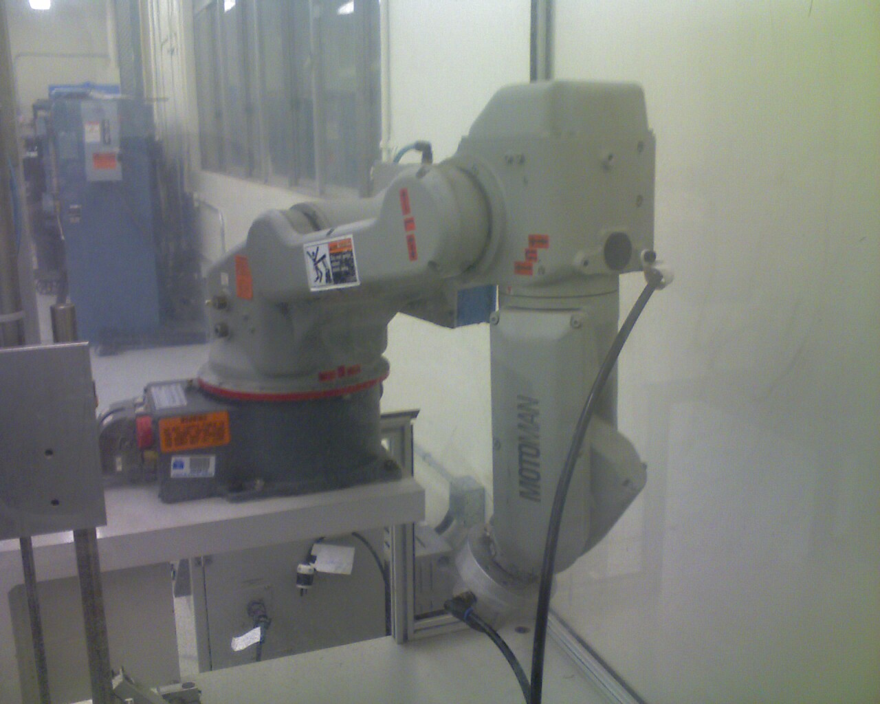
The Motoman SV3 is a compact 6-axis industrial robot. It is used in small part applications such as welding
and assembly. Recently MAE Department at Cal State Long Beach received this robot as industrial donation. The power supply
cables had been cut from the moving process and the robot is in non-operating condition. There are two professors in MAE department
that are taking care of this robot; Dr. Pannada Marayong and Dr. Bei Lu. These professors offered two project topics for Electrical
Engineering students through our professor Dr. Hamano. Our team was interested in this project and started to work on it with
the Professors’ consent. Our team basically research on how to restore this robot to its working condition. This robot
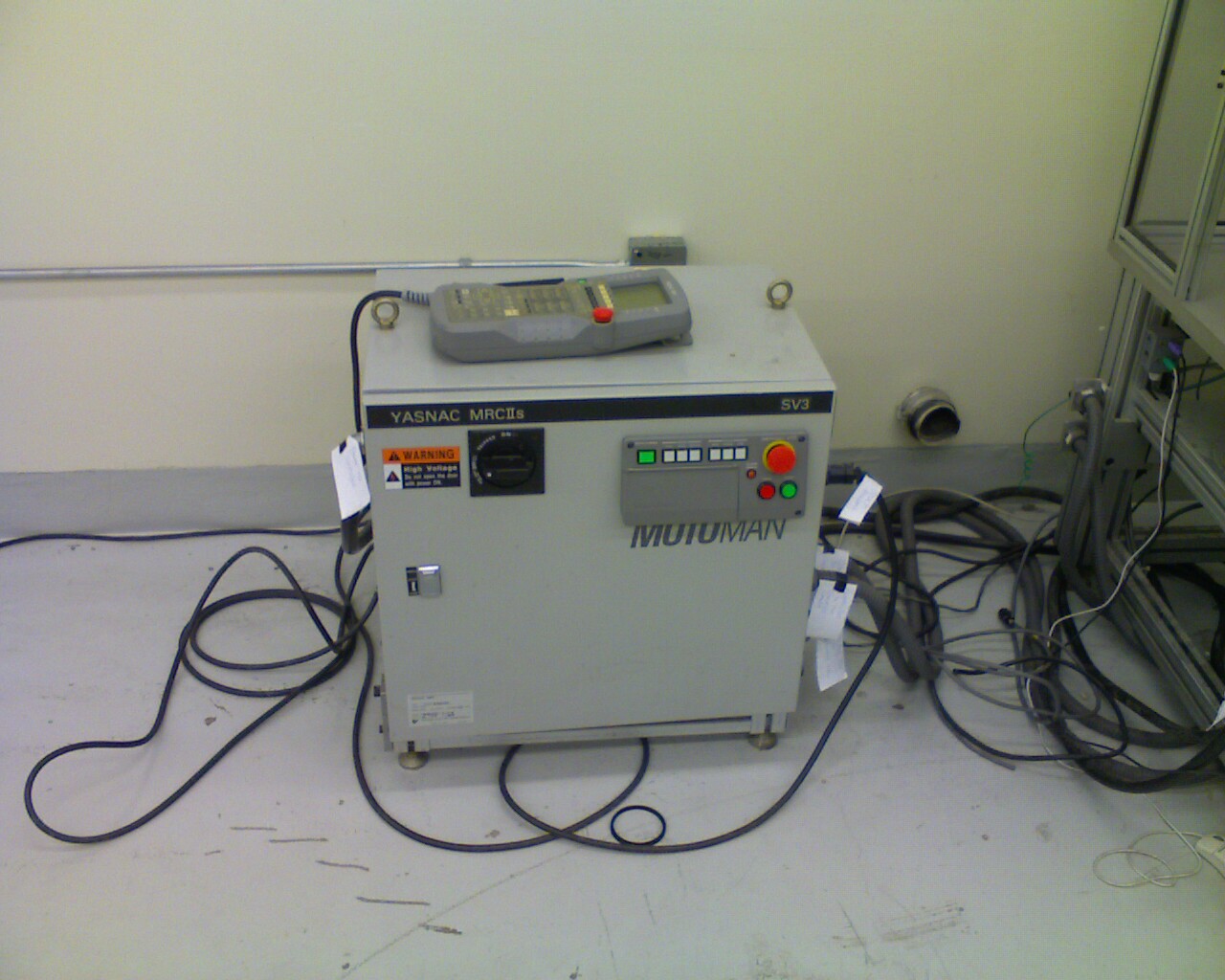
comes as a system that includes YASNAC MRCII controller, manipulator and teach pendant as shown in Figure1 and Figure2. It
has its own power supply (220V). It also came with extra hardware, a computer (CPU unit and monitor) located in the same chamber
as the manipulator, and controllers located adjacent to this CPU unit. These controllers are known to interface with this
computer and conveyor belt.
Figure 1. Manipulator
Figure
2. MRCII Controller and the Teach Pendant
Project Goals and Tasks
As mentioned, the power cables were cut and those definitely need to be repaired. The project goal is to bring the
system back to a working condition. According to the assumptions made at the start of the project, the Professors suggested
that the robot is in working condition with the exception of connecting the power cables. So first task was to get those cables
repaired and test the operation of the robot by designing a simple task using teach pendant. If the robot still does not work,
then the second task would be to research through available resources(system manuals, specification sheets, technical support,
etc.) to develop or propose a solution for repair needed to restore the robot to its operating condition.
Approach
Since we came across several different problems
while working on this project, we divided the above mentioned tasks into three different stages. We are going to explain in
detail, the problems and solutions in each stage. As for the extra research that we have done in this project, we will present
some of our findings that can be found in the appendix section of the report.
First Stage Problems and Solutions
The first stage problem
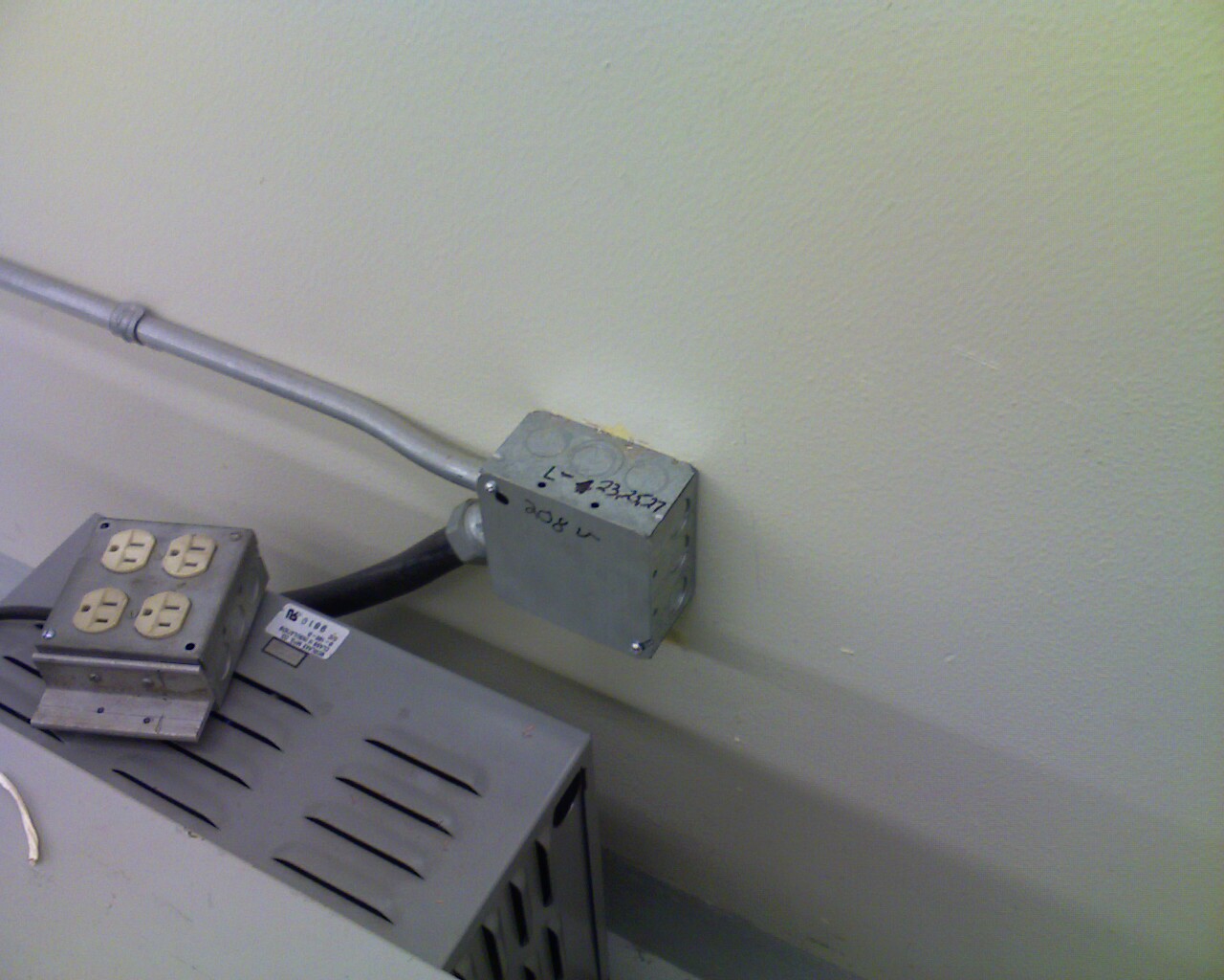
was that all the power cables were cut. The controller comes with a transformer(480-220V). It looks like the previous owner
of this robot was using 480V outlet. According to the manual, the controller power supply is 220VAC, 60Hz. So we started a
work order with the help of Professors to repair the cables. The electrician actually bypassed the transformer and put a new
220V outlet. The controller was then hardwired to this outlet as seen in Figure 3. One thing we would like to mention here
is that this process took some time and there were delays in getting the outlet ready. So in the meantime, the professors
suggested us to think about the task that we will design assuming that robot will be working after it gets power. The robot
comes with all the manuals including controller, teach pendant, software, etc. We read the manuals and prepared for the test
run also mentioned in the YASNAC MRCII controller manual.
Figure 3. 220V Outlet
Test Run
The next step was the test run. We check all the
cables and made sure the controller and the manipulator interface correctly through the power cables (1BC and 2BC). These
two cables connect the servo pack inside the controller to the manipulator. Also we did a safety check(no loose wires) and
one of our members remain close to Emergency Stop(red button) so it could be pressed at any time. We turn on controller power
first as was mentioned in the YASNAC MRCII controller manual. We could hear the controller getting started and it looked like
it would work.
Second Stage Problems and Solutions
The teach pendant was supposed to display a title screen after initial diagnosis if everything was normal. But that
did not happen. Instead we got an alarm message. The alarm message read “Alarm 200 Fault parameter…RC Robot Conform
Parameter” as also can be seen in Figure 4.
Figure
4. Alarm 200 Fault Parameter
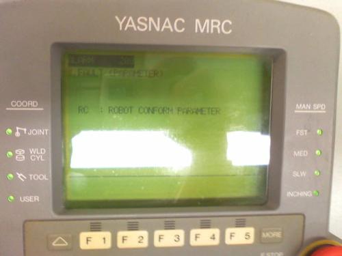
According to the manual, the parameter file in CMOS memory is destroyed. This parameter RC is
actually a system parameter known as Robot Conform parameter. The manual suggests that we initialize this parameter file in
customer maintenance mode. Then load stored parameters from floppy disk. We also contacted Motoman technical support on this
problem. They pretty much suggested a similar procedure as the manual. We will list their procedure with no change as follows.
Procedure To Initialize MRCII
NOTE: PRIOR TO CONDUCTING THIS PROCEDURE, ENSURE ALL MRCII INFORMATION
IS SAVED TO DISK!!
1. 1.
Ensure MRC power is off prior to performing the following.
2.
2. Turn the rotary switch on the MCP10 to 7 and turn on MRC controller power.
3.
3. Select SETUP SYSTEM using the cursor up/down keys and press ENTER
4.
4. Select SYSTEM CONFIGURATION using the cursor up/down keys and press ENTER on the
PROGRAMMING PENDANT.
5.
5. Select INITIALIZE using the cursor up/down keys and press ENTER on the PROGRAMMING PENDANT.
6. 6.
You will now be ask a number of question pertaining
to the configuration of your system answer each by cursoring up/down left/right
and pressing ENTER on the PROGRAMMING PENDANT after selecting the appropriate answers.
7. 7.
After answering YES to the final “are you sure
question”, power down the controller and power back-up
8. 8.
Re-load all MRCII Data, system is now ready to run.
We could only do this procedure provided other parts of the controller are getting power. These parts including servopacks,
playback box, etc. ,were all off. This led us to believe that there is power interface problem within the controller itself.
We opened up the controller box and noticed a small battery inside the controller as shown in Figure6.
Figure 6. Controller Battery
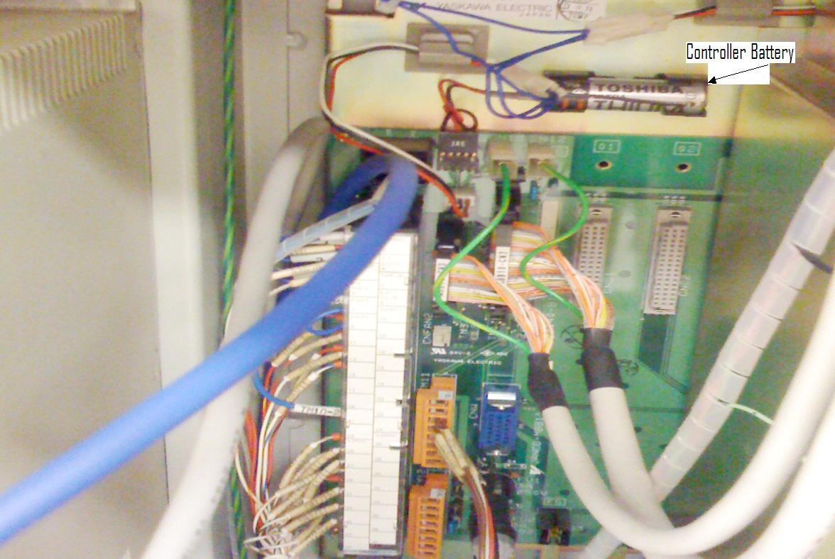
Controller Battery Issue
We found out that this battery is responsible for backing up the CMOS memory and absolute encoder.
It is 3.6VDC Toshiba Lithium battery. Hence a major problem was found and we need to replace this battery before we can correct
Alarm 200 message. This also comes together since a parameter file RC was destroyed in CMOS memory and this battery backs
up CMOS memory. So our interpretation is that it is very likely that dead battery caused the RC system parameter to be destroyed.
Also to check and replace the battery when needed is one of the regular inspections
that the manual suggest.
So our primary conclusion for this stage is that this battery should be replaced before any further
analysis can be done on the robot. The next step would be to reset the internal computer via its firmware disks (No disks
located on site). We see some floppy disks but those we believe are for the additional computer that the robot came up with.
Servo Pack seems to have problem in term of Input power. This might be solved
if the internal computer is in operating condition.
Third Stage Problems and Solutions
This stage is basically concerned with the additional
hardware that the robot system came up with. Interfacing computer below the SV3 manipulator also display error message. This
computer is known to interface with the conveyor. This error message was due to booting sector corrupted. In order to get it working, we would have to re-install the window NT operating system. The problem could
be more than that. In fact one of the technicians looked at the CPU unit and he suggested it is pretty dead. So we might have
to replace the whole CPU unit. We would only fix it considering that we want to interface with the conveyor also. Logically,
we could bypass this interfacing computer and the SV3 Robot system is still working.
Summarizing Critical Problems and Future Plan of Action
Þ Þ Error message “Alarm 200 Fault Parameter
Þ Þ Corrupted Bootable Files in the interfacing Computer
Þ Þ No power
Provided to the Servo Packs
Þ Þ SV3 Manipulator
Arms can not operate
Þ Þ Battery
of the internal computer must be replaced
Þ Þ Full reset of the internal computer must be done before
any further trouble shooting.
Conclusions
We learnt a lot of
things working on this Motoman robot. Firstly we got hands on experience working with an industrial robot. Secondly we related
our knowledge learned in our class 474/474 to this real world robot. We also saw how much effort and time it takes to produce
a working robotic system. In the beginning, we were thinking that we will just see a robotic arm, but what we saw was a complete
system with a huge controller, teach pendant and robotic platform that can interface with other machines or robot. We were
simply amazed how detailed this robot was, and three big manuals did not seem enough to cover this system. We also appreciated
the work of great minds that have made this system possible. Thus this robotic system seems to cover all aspects of engineering
fields including mechanical, electrical, control systems, power, etc. Apart from working on this project, we also enhanced
our communication skills by working as a team. There was a strong interaction with the faculty and other personnel involved.
We also enhanced our time management, project management and research skills. In a nutshell, a great project that provided
so much learning and experience and we feel lucky to have worked on this robot.
Operational Block Diagram
of the Robot
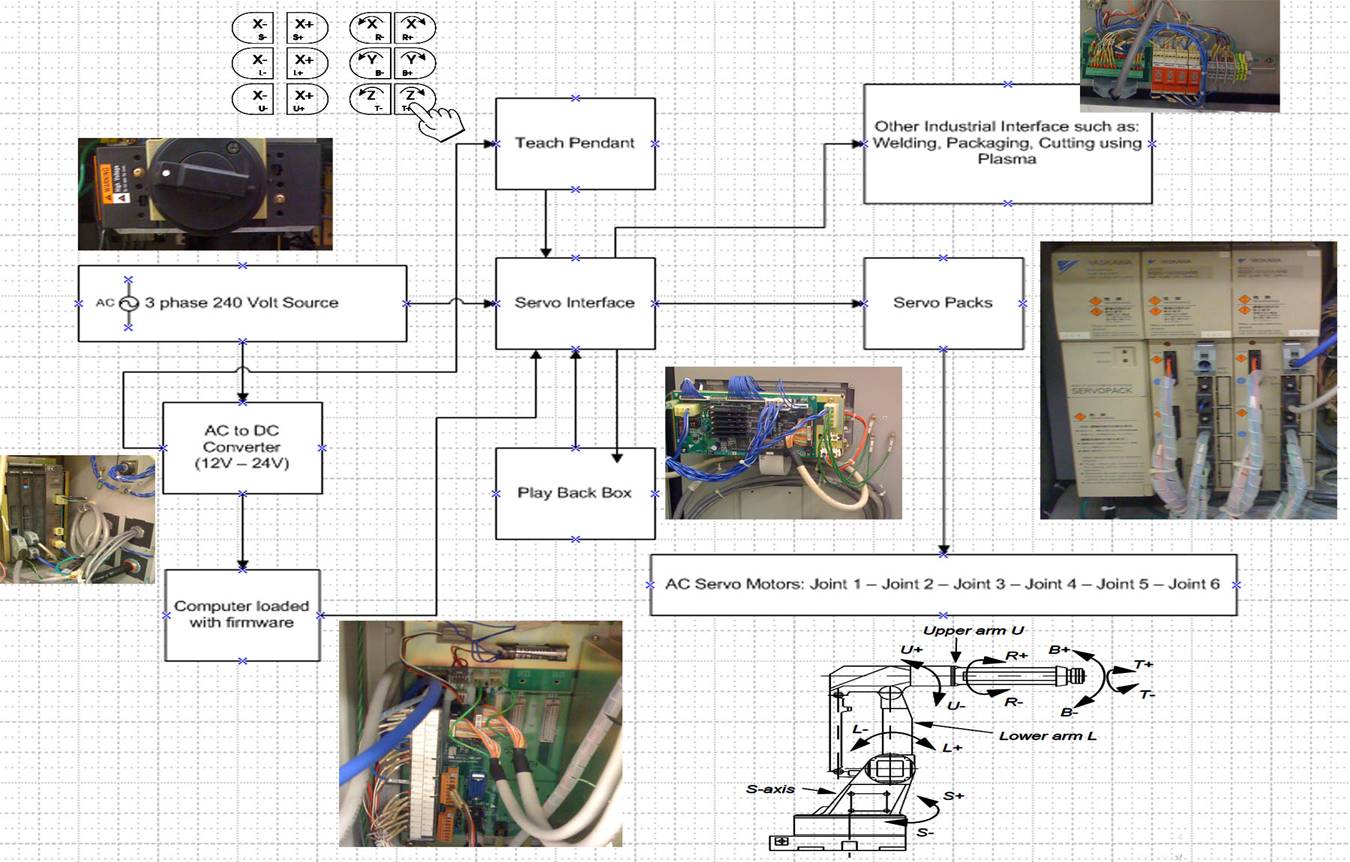
The power source of
the robot system is fed by a three phase, 240 Volts supply. This power supple
is distributed to the main blocks of the system such as, the servo interface block, the AC to DC (12v-24v) converter, supplying
DC voltage for the internal 32 bits computer. The teach pendant is connected
directly to the servo interface block. This teach pendants’ main operation
is to obtain the instructions from the user and deliver these instructions to the servo interface, which then direct the servo
packs to move the six axis manipulator arms. The servo pack located inside the
main control cabinet. This servo pack is responsible in term of controlling the
manipulator electrically. It provides the precise power, pre-defined according
from the manufacturer’s firmware, to the manipulator arms. The play
box which located in front of the control cabinet allow user to select the play back option or program. This program is a set of instructions that user previously inputted through the availability of the teach
pendant. The robot system also equipped with the electro magnetic interference
filter, this special filter located behind the power switch eliminate the EMI interference and assure the robot system always
receive the clean power throughout its operation.
Design of Simple Task
Using Teach Pendant
Figure 2.00. Controller
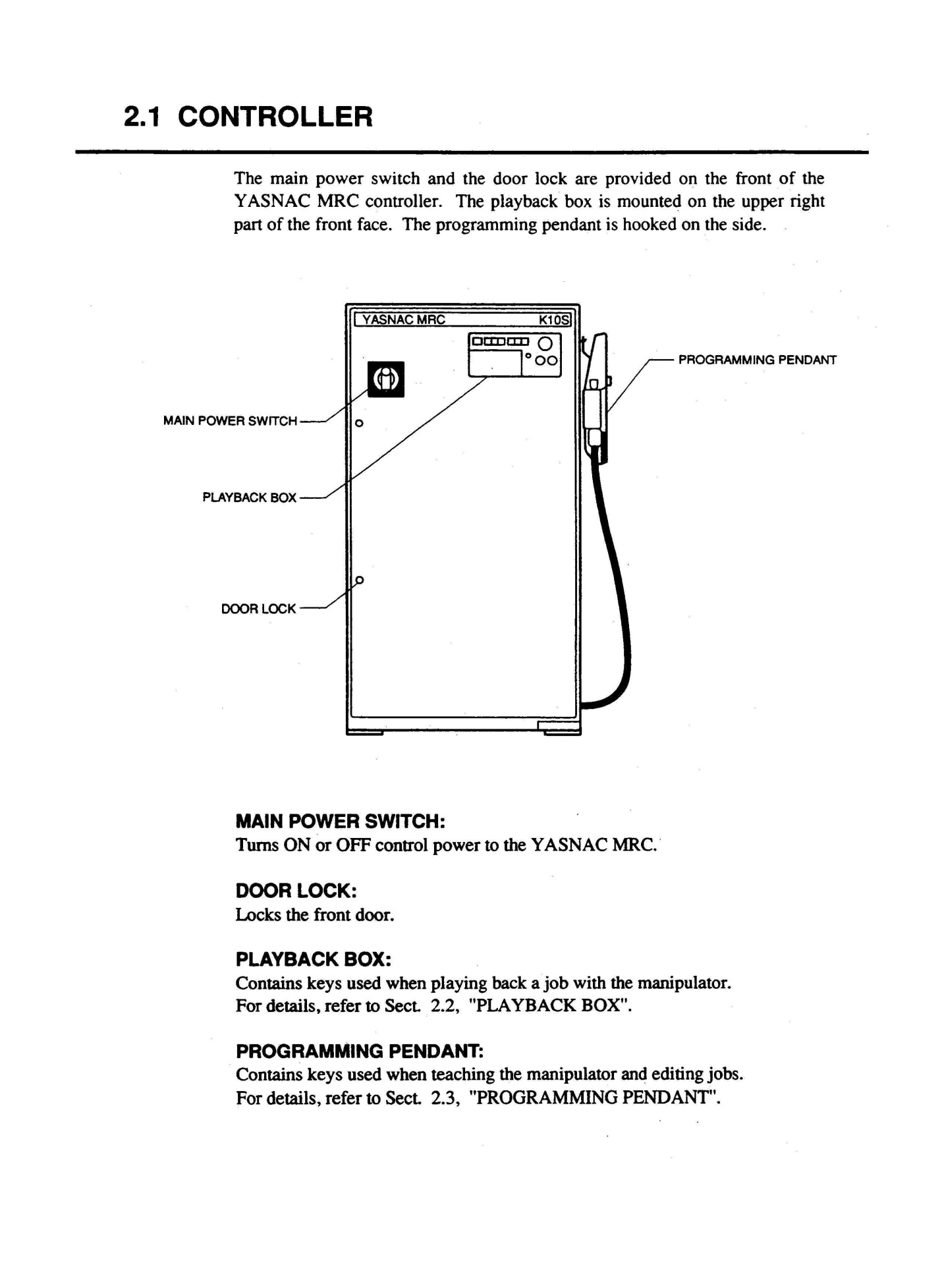
Figure 2.10. Playback Box
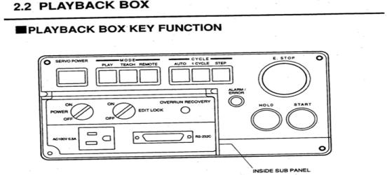
Figure 2.20. Flow Diagram
for Programming Pendant shown.
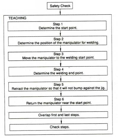
Figure 2.30. Programming
Pendant
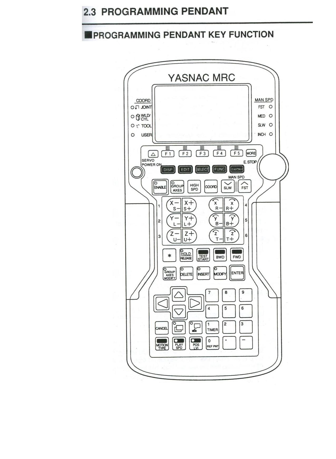
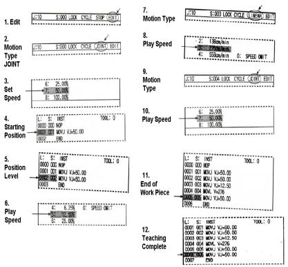
Figure 2.40. Sample of Programming Code
Start up:
To begin to teach the Motoman we turn the main power switch clockwise to turn on the power, and
set the robot manipulator for teach mode. To teach the robot manipulator you
press the teach button on the playback box. Press F1 to enter a job name, press
F2 for a new job, and then press enter on the programming pendant to begin teaching the robot manipulator.
Teaching a job:
Press EDIT,
and then press ENABLE on the programming pendant. Pressing the enable button
allows you to move the robot manipulator with the axis keys located on the programming pendant. Using the axis keys move the robot manipulator to the desired starting position. You can press and hold the high speed button with the axis key for faster movement. After the starting position has been set press the ENTER button to set the next desired position.
Next we set
the robot manipulator to the desired cutting position using the axis keys. This
is not on the work piece. The robot manipulator should be the same level as the
work piece but at a distance. Press enter, and press either FST or SLW on the
programming pendant to set work piece for fast or slow approach speed.
Move the robot manipulator using the axis keys to the start point on the work piece.
Press the PLAY SPD on programming pendant for selecting the approaching speed, and then press ENTER to next desired
position. Move the robot manipulator with the axis keys on the programming pendant
to the end position on the work piece. Press MOTION TYPE on the programming pendant. You can then select three different types of motion.
The first motion is a linear motion, the second is circular motion, and the third is a spline motion. From not having a working robot manipulator we choose a linear motion.
If the robot manipulator was working circular motions would be more advanced and require more programming from the
pendant. So from trial and error a circular motion could be possible for a working
robot manipulator. After selecting the motion press PLAY SPD on the programming
pendant to select the cutting, grinding, etc. speed, then press Enter, and press FST or SLW on the programming pendant to
set speed. Next set the robot manipulator to desired position away from the work
piece using axis keys on the programming pendant. You can select MOTION TYPE
on the programming pendant to have the robot manipulator move in a certain path away from the work piece. We choose a linear motion, press PLAY SPD to set the moving away speed, and the press ENTER. The programming of the robot manipulator is complete.
Play Back:
To play the programming steps press PLAY, press 1 CYCLE, and START on the playback box.
To Stop:
To stop the robot manipulator press ESTOP on the playback box or programming pendant to turn off
power to the servos. Turn the main power switch counter clockwise to turn off
the power.
Project Progress Log
Although we worked on this project for 3-4 weeks,
we did not always meet in the lab. Our team consists of four members and sometimes it was hard to get everyone on the same
page. Therefore a lot of communication was taking place through email discussion especially with the professors Dr. Marayong
and Dr. Bei Lu. We just like to summarize how the project progresses over time. Timeline is Nov.2008-Dec2008.
Tuesday, 9 December
After we
look up the robot, we realize that all the solutions correspond the problems we have are necessary based on one major situation-All the Servo Pack should be powered up The SERVO POWER Key should be lit when it is activated and the Servo Pack
is ON. However, when we tried to activate the SERVO POWER button, the key is not lit => It looks like the Servo Pack did
not have any power. According to this, there can be additional problem that we have to explore and is our primary goal
to achieve.
Saturday, 6 December
After Cuong
Le contact the Motoman People, they gave us some directions on what we should do on the error message 200. He also able to
obtain the service manual of the MRC SV3 Controller. According to the Motoman people, we are dealing with execution
file corruption when Controller starts to boot up. Their solution is to reset the program by using the teach pendant.
Hopefully we will have some response when we meet next week. We also find out that the computer which Dr. Marayong mentioned
about is responsible for interfacing with other machine. On the other word, the computer has nothing to do with the robot
arm; the MRC Controller should be enough to operate the Arm of the Robot.
Thursday, 4 December
Dr. Panadda
went down to check the computer with the technicians. It seems that the computer is pretty dead. So here is what Dr. Panadda
suggests us do: Do a research (on the net or contact someone from Motoman) of
how we can update the CPU unit. There should be some examples of a working SV3 system with more up-to-date computer. We should
be able to by-pass all the extra hardware that came with the robot and just get the robot working. It might be as simple as
replacing the CPU unit and reinstall the software.
Study and
make a note the operation of the robot controller, the computer, etc. I want to know what all the cables are and how each
component communicates to each other. Please find out and put a label on each cable between the controller box, the computer
unit and all of the devices. A diagram showing the work flow would be useful. This will help us decide what we need and what
can be replaced.
Monday, 3 December
According
to the manual, we find out the error message: Alarm 200 Fault parameter means the parameter file in CMOS memory is destroyed.
We will try to figure out the solution in the manual. But we are still not sure
about the other error message: Stop: c0000135 Unable to locate DLL.
Tuesday, 2 December
The robot and the computer (located
underneath the robot) now have power. However, they are still not working. When we turned the controller on, the control seems
to receive the power but the green light doesn't come on. The teach pendant displayed the following error message: Alarm 200
Fault parameter. The computer can be turned on but is stuck with the following error message: Stop: c0000135 Unable to locate
DLL. We speculate that each of them might be waiting for some signal from other sensor/components that are no longer connected
to the robot and the computer. So our tasks:
Check all
the cables. There are a few cables that we are not sure where they connect. Figuring
out what is the problem and try to get the teach pendant to work again. It might be that we have to reinstall all of the drivers.
There are a whole bunch of floppy disks in the manual left in the lab which we think can be used to reinstall all of the programs
Saturday, 22 November
The electrician
came to add the power outlet today. He will hard-wire the control box to the wall outlet and bypass the transformer. According
to him, it should be finished by today. So the robot should be ready for us to test out on Monday.
Wednesday, November, 19
The technicians bypass the transformer and put a 220V plug for the controller. However, we find
out another problem that the wall outlet has no power. The technicians will fix it and try to finish by early next week.
Tuesday, 11 November
The technicians move the robot in the room where we need it and have started a work order to add
a disconnect box. Hopefully, the facility people will get around finishing everything by the end of the week or maybe early
next week. In the mean time, we started to look up the manual and find out how to do the test run after the robot has power.
Monday, 3 November
Dr. Panadda asked technicians to move the robot to where the outlet is and hook up the wires.
However, the technician didn’t finish the jobs, so there is no power to activate the robot. In the mean time, we started
reading up on the system, how to use the teach pendant and think about what task we want to design.
Friday, 31 October
Muhammad Anees, as the team leader, contacted Dr. Panadda and told her we are interesting to do
the project-Motoman Robot. Furthermore, we decided to meet every Monday at 4pm and our
first meeting is on Nov. 3.
References
- 1. Most of the materials in this report is obtained from Motoman MRC II, SV3 Manuals. Motoman is
designed by MOTOMAN Robotics AB, a subsidiary of YASKAWA Corporation.
- 2. Few researches on the Web for further understanding of the robot system.
End of MOTOMAN SV3 Revamp Project.
|