|
Hybrid Solar RC Vehicle
Contents:
What
is a fossil fuel?
A fossil fuel burning car is difficult to switch to a solar
car because of its worldwide use of the internal combustion engine. Fossil fuel
has been around longer than solar energy is another reason for a difficult switch. A
fossil fuel is the energy from the remnants of animals and plants that have not decomposed.
This means that carbon is still stored in fossil fuels and when burned the carbon is released. These remnants are trunks, algae, plankton, and forest thousands of years or older where bacteria has broken
them down into natural gas and crude oil. When the fossil fuel is burned in the
internal combustion engine a chemical reaction occurs. At equilibrium this reaction
produces carbon dioxide gas and liquid water. At non-equilibrium this reaction
produces harmful gases such as nitrogen dioxide and carbon monoxide gases. These
types of gases are bad for our health and bad for the environment. These gases
are a contributor to pollution that cause heart and respiratory problems and may cause cancer.
Symptoms include eye and throat irritation, heavy breathing, to more severe symptoms such as birth defects, brain,
and nerve damage, and even death. The Environmental Protection Agency or EPA
has a pollution index to monitor the levels of pollution for residents and schools in problem areas. It is morally wrong to have children, the elderly, and adults reduce outdoor activities because of the
pollution from using fossil fuels in internal combustion engines. On very hot
and humid days where pollution is the worst people will have to stay inside and breathe air from oxygen masks. People should have the opportunity to work, play, and exercise in a pollution free environment.
Fossil Fuels and Carbon-Dioxide
Carbon dioxide is a greenhouse gas and burning fossil fuels
from an internal combustion engine causes a large portion of carbon dioxide gas. The
United States is the number one producer of carbon dioxide, while China is second, Germany is third, and Japan is fourth. Studies found from ice samples before industrialization showed carbon dioxide levels
were lower than after industrialization; this coincides with burning fossil fuel in cars.
On earth the carbon dioxide gas traps in heat. From heat being trapped
inside the earth the temperature of the ocean water increases. This warming temperature
is known as global warming. As the temperature increases the polar ices caps
melt causing sea levels to increase. Increasing sea levels cause countries in
the Caribbean, and Pacific islands to become submerged under water. Since the
United States is surrounded by ocean water many coastlines will disappear. Beaches,
birds, seals, and polar bears will no longer exist.
Warm ocean currents from the India Ocean exchange temperature
with cold Atlantic Ocean current near Europe. Having an increase of ocean temperatures
can cause the temperature exchange to break its cycle. A break in this cycle
can cause Europe to freeze because in the winter Europe depends on the temperature exchange from India's ocean to stay warm
during the winter months. It is morally wrong to have this kind of worldwide
effect. People will be displaced form their homes, crops will fail, panic will
develop, and disease will spread. People should be able to live lives without
this kind of disaster caused by carbon dioxide.
A Possible Solution
Resolving the issues of health problems with pollution and
the threat of global warming my group members and I have thought about a plan to eliminate these issues and came up with a
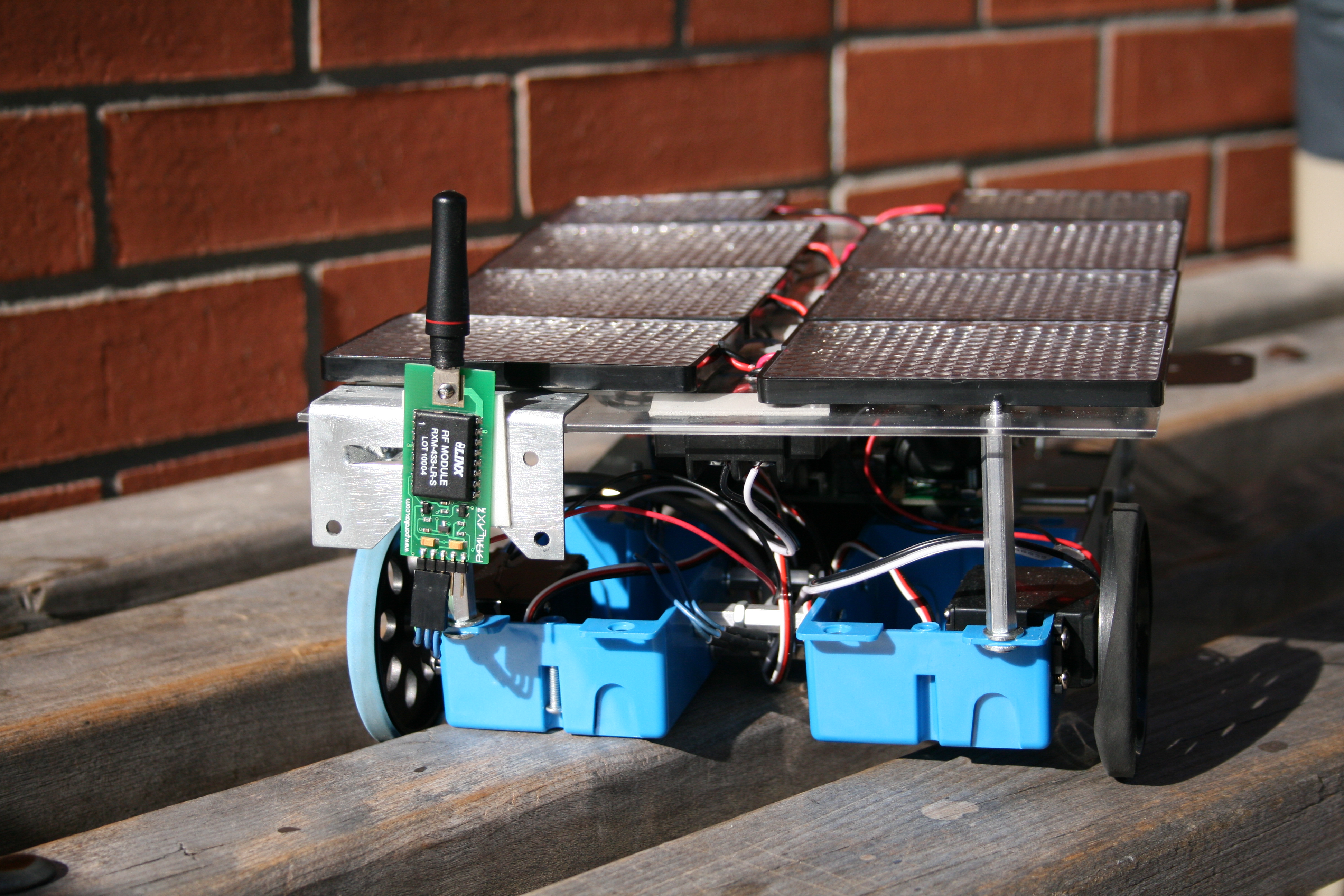
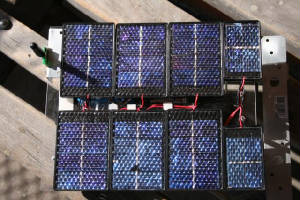
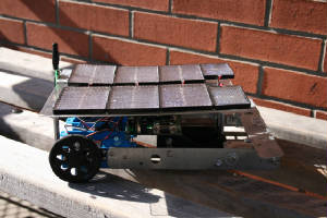
feasible design to resolve the issues. The design is a solar car that runs on
battery power. This design is a true zero emissions car because the solar panels
are used for charging the battery. No relying on a fossil fuel burning power
plants to charge the battery; only clean renewable solar energy is used to charge the battery.
Why Solar?
This design would
not contribute to pollution because of the use of an electric motor instead of an internal combustion engine. The design eliminates the need of running on fossil fuels and does not use a chemical reaction the way
an internal combustion engine does. So gases such as carbon dioxide, nitrogen
dioxide, and carbon monoxide will no longer be of concern. With no gases children,
the elderly, and adults will no longer be at risk for air quality and can continue their outdoor activities. If the United States were to switch to a solar car the ranking of carbon dioxide produced by the United
States would go down and the United States would be a world leader in renewable energy.
Having a lower emission of carbon dioxide reduces greenhouse gas and the threat of global warming. This design would be very effective because most of the people who drive internal combustion engines travel
short distance such as traveling to the store and then back home. This is a waste
of money and non-renewable resources. This design would meet the need to travel
those short distances and with improving technology such as running time and charging time for the battery the design could
be used for longer travel distances.
Controls
A two axis joystick
is used to control the project. The joystick consists of a mechanical arrangement allowing position to be measured in each
axis through a potentiometer.
The resistance across each potentiometer can be
measured using the BS2’s RCTIME command.
Communication
The Parallax 433.92 MHz RF transmitter
and receiver modules were chosen in the interests of efficient interfacing with the BS2. The two modules communicate using
RS-232 serial protocol which is masked by the BS2’s built in SERIN and SEROUT commands.
Our system is configured to operate at a 9600 baud rate, inverted.
-
Theory of Operation
-
Transmitter Connection
-
Receiver Connection
Theory of Operation
Short for Radio Frequency, RF refers to the frequencies that fall within the electromagnetic spectrum associated with
radio wave propagation. When applied to an antenna, RF current creates electromagnetic fields that propagate the applied signal
through space. Any RF field has a wavelength that is inversely proportional to the frequency. This means that the frequency
of an RF signal is inversely proportional to the wavelength of the field. The Parallax RF modules utilize a frequency of 433.92
MHz, this works out to be a wavelength of approximately 0.69 meters (2.26 feet, or 7.3e-17 lightyears). 433.92 MHz falls into
the Ultra High Frequency (UHF) designation, which is defined as the frequencies from 300 MHz ~ 3 GHz. UHF has free-space wavelengths
of 1 m ~ 100 mm (3.28 ~ 0.33 feet or 1.05e-16 ~ 1.05e-17 lightyears).
Transmitter Connection
*Picture Modified From Parallax documentation
Receiver Connection
*Picture Modified From Parallax documentation
Calibration
When initiating communication between the RF modules, a sync pulse should
be sent to re-establish the radio connection between the modules. Sending several characters can accomplish this, however
sending a pulse (which maintains a high state during the synchronization) is more efficient.
Data
Packet:
The data sent will consist
of an unique indicator byte, in our case an exclamation point (!), which will be followed by the 8bit components of two 16bit
integers containing the x and y axis readings from our transmitter. The data will be followed by a checksum to verify its
accuracy.
6
Bytes Total
|
“!”
(Hex 21) |
High |
Low |
High |
Low |
Checksum |
|
X Axis Position |
Y Axis Position |
Drive
The project is propelled by dual servo motors
driving its two rear tires. Originally our design called for brushless dc motors with an H-bridge interface; it was found
however that the necessary torque could not be generated using this design. Instead we opted for servo motors which were internally
geared to provide greater torque without demanding additional power from the system. The two servos were purchased from the
parallax website in the hopes they would easily interface with our BS2. Originally manufactured by Futaba, our servo selection
proved exceedingly easy to integrate and control.
The
Futaba S148 can be described by the following specifications:
- Power 6vdc max
- Average Speed 60 rpm
- Note: with 5vdc and no torque
- Weight 45.0 grams/1.59oz
- Torque 3.40 kg-cm/47oz-in
- Size mm (L x W x H)
40.5x20.0x38.0
- Size in (L x W x H)
1.60x.79x1.50
- Manual adjustment
port
The servos are controlled using the BS2 located on
the vehicle. The direction and speed of each motor may be controlled using pulse width modulation at a signal of 50Hz. Practically
this is implemented using the BS2’s PULSOUT command to send a high digital “high” signal to the device for
a specified duration, followed by a reciprocal “low” using the PAUSE command. If the ratio of “high”
to “low” in the signal is even the servo remains stationary. Signals with a larger portion of “high”
will rotate clockwise, and likewise signals with a larger portion of “low will rotate counter clockwise.
At rest:
|
ß
10ms à |
ß
10ms à |
|
|
|
|
|
|
|
|
ß
20ms
à |
|
|
Clockwise:
Counter-Clockwise:
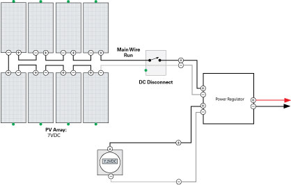
Power System
Power Requirements
The Hybrid Solar RC Vehicle comprises of several
loads
1.
Microcontroller – 5V @ varied Amperage
2.
Servo – 6V 200mAh @ full load
3.
Radio Control Receiver – 5V @ 5.1mA – 1.8mA
4.
Power Controller – 5V @ 2mA
The HS-RC Vehicle contains two power sources.
- Battery: 7.2 volts @ 600mAh
- Solar: 7.2 Volts @ 400mA (at full irradiance 38°)
- Analysis
- Solution
-
Schematic
-
Disrtibution of the Circuit
-
Design Layout
Analysis
The Hybrid Solar RC Vehicle is
designed to make use of the sun's power with a batter backup bank. During low irradiance the system switches to batter and
during high irradiance the system makes use of the sunlight. The system works best during the high sun times of the day (11am
to 2pm). This is especially true during the summer months when the azimuth angle of the sun relative to a stationary body
is much higher. The result of a larger azimuth angle is the ability of the sun’s irradiance to hit the solar cells at
a perpendicular angle (90degrees)
One of the challenges is to obtain perfect perpendicular exposure to the solar cells. We experimented with pitching
the cells with increased position angle, however, weight distribution became a problem and we settled on a solar plate to
body angle of 32 degrees. A perfect apparatus would have a miniature gyro that would follow the angle of the sun as a function
of irradiance, direction and time of day.
Solution
The HC-RC was equipped with a
power distribution device that appropriates adequate power depending on the irradiance of the sun. As our analysis suggests,
irradiance is not a constant. Therefore a battery pack with the ability to charge during high irradiance, and switch sources
to compensate for power needs was essential to the final solution. However, due to the weight concerns, we were unable to
create a system the charges the onboard battery in times of high irradiance. Our solution settled on a component that has
the ability to choose power sources using a comparator circuit.
Schematic
Below is the schematic for the distribution circuit.
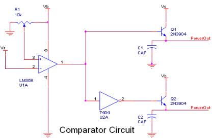
Vs
– Solar Voltage
Vb
– Battery Voltage
Dstribution of the circuit
The LM358 Op-Amp acts as a comparator. The reference
voltage is Vb and Vs acts as the test voltage. The system was manually configured for threshold by adjusting a variable resistor
to reach a cutoff voltage. The output of the OP-amp controls two digital switches that control the use of Power sources.
The RC Circuit was determined
by a Pspice Simulation and compared to an Excel analysis. The output which appears below directed the design of the apparatus.
Accordingly, C1 & C2 are rated at 220uF with a resistor placed in series rated at 2.2k ohms.
|